以机器人智能柔性制造系统为主的现代制造技术近年来在全球范围发展极其迅速,尤其是在重型、高端装备制造业上的发展更为广泛。美国沃特飞机公司研制了一套机器人钻铣系统,用于完成波音737内侧襟翼的钻孔和铣削工作[1]。浙江大学研制了一套集成激光测量技术、计算机控制技术、离线编程技术和机器人技术的自动化制孔系统,大幅度提高了飞机部件的制孔效率[2]。针对大型球状工件复杂孔系制造,天津大学研制了一套KUKA工业机器人位姿测量与在线误差补偿系统,提高了位姿精度[3]。工业机器人定位精度高低直接影响了上述系统的制造质量和效率。
航天器超大结构产品具有尺寸大、质量大等特点,其舱体组合加工超过了现有加工设备允许的尺寸上限,导致研制过程需要大量人力,造成产品一致性差、品质不稳定,自动化程度低等问题[4-5]。机器人智能柔性制造系统为上述产品制造瓶颈提供了一种全新的思路。工业机器人本体机构在制造和安装过程中存在微小误差,经过串联机构逐级放大,最终产生较大的末端位姿误差,需通过运动学参数的辨识,实现对本体机构加工和安装误差的补偿[6-7]。高文斌等[8]给出了指数积形式的机器人距离误差模型,采用激光跟踪仪,完成了对一种5自由度机械臂运动学参数辨识实验,取得了好的实验效果。天津大学叶声华研究团队对机器人本体精度标定方法不断研究,利用激光跟踪仪,分别采用基于各轴单独旋转拟合空间曲线的方法[9]、线性方程最小二乘解方法及距离精度评价方法[10]进行精度优化,实现了机器人运动学参数的辨识,取得了很大进展。API公司采用激光跟踪仪结合Denavit-Hartenberg (D-H)算法软件实现机器人标定与评价,可将机器人定位精度提升一倍[11]。采用上述方法进行运动学参数辨识时,位置与角度误差往往是同时辨识,由于物理含义不同,那么误差数量级较小但对加工精度影响很大的角度误差非常容易淹没在数量级较大的位置误差中,将导致辨识精度降低。
鉴于目前工业机器人运动学参数辨识方法中对于角度误差与位置误差未进行区别分析,论文从工程应用角度出发,构建工业机器人运动学模型,提出两步误差模型进行运动学参数辨识,而后修正机器人D-H参数,进而完成碳纤维薄板钻孔。
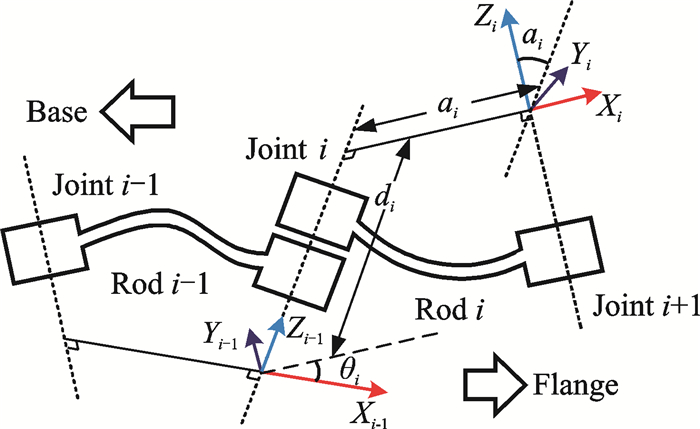
1 工业机器人运动学模型构建以Kuka KR500机器人作为研究对象,建立D-H模型,如图 1所示为D-H模型示意图。对于6自由度串联机器人,设与连杆i连接的坐标系OiXiYiZi为Oi。坐标系Oi相对于Oi-1的位姿用4个参数描述(如图 1所示),且满足如下要求:(1) Xi-1轴到Xi轴的夹角为关节转角θi,绕Zi-1轴正向为正;(2) Xi-1轴到Xi轴的距离为关节距离di,沿Zi-1轴正向为正;(3) Zi-1轴到Zi轴的距离为连杆长度ai,沿Xi轴正向为正;(4) Zi-1轴到Zi轴的夹角为连杆扭角αi,绕Xi轴正向为正;(5) Xi轴垂直于Zi-1轴,Xi轴垂直于Zi-1轴相交。

|
图 1 D-H模型 Figure 1 D-H model |
坐标系Oi-1经过以下坐标变换转到坐标系Oi:绕Zi-1轴转动θi;沿Zi-1轴移动di;沿Xi轴移动ai;绕Xi轴转动αi。因此D-H描述的齐次变换矩阵为Ti,i=1~6。
| $ \begin{array}{l} {\mathit{\boldsymbol{T}}_i} = {\rm{Rot}}\left( {z, {\theta _i}} \right){\rm{Trans}}\left( {0, 0, {d_i}} \right){\rm{Trans}}\left( {{\alpha _i}, 0, 0} \right){\rm{Rot}}\left( {x, {\alpha _i}} \right) = \\ \;\;\;\;\;\;\left[ \begin{array}{l} \cos {\theta _i}\;\;\;\; - \sin {\theta _i}\cos {\theta _i}\;\;\;\;\sin {\theta _i}\sin {\alpha _i}\;\;\;\;{a _i}\cos {\theta _i}\\ \sin {\theta _i}\;\;\;\;\;\cos {\theta _i}\cos {\alpha _i}\;\;\;\; - \cos {\theta _i}\sin {\alpha _i}\;\;\;{a _i}\sin {\theta _i}\\ \;\;\;0\;\;\;\;\;\;\;\;\;\;\;\;\;\;\sin {\alpha _i}\;\;\;\;\;\;\;\;\;\;\;\cos {\alpha _i}\;\;\;\;\;\;\;\;\;\;\;\;\;{d_i}\\ \;\;\;0\;\;\;\;\;\;\;\;\;\;\;\;\;\;\;\;\;0\;\;\;\;\;\;\;\;\;\;\;\;\;\;\;\;\;\;0\;\;\;\;\;\;\;\;\;\;\;\;\;\;\;\;1 \end{array} \right] \end{array} $ | (1) |
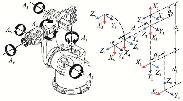
依据上述D-H模型参数定义,提取Kuka KR500机器人模型中相关参数(如表 1所示),建立相应D-H模型,如图 2所示。根据正向运动学求解得到末端法兰盘坐标系到机器人基坐标系的坐标变换矩阵0T6=0T11T2 2T33T44T55T6。
| 表 1 KR500-R2830型机器人理论D-H参数 Table 1 Theoretical D-H parameters for KR500 robot |

|
图 2 Kuka KR500机器人D-H模型 Figure 2 Kuka KR500 robot D-H model |
2 基于两步误差模型的运动学参数辨识
机器人运动参数精度受机械加工精度、装配误差、磨损、传动误差、负载变化和环境等影响,造成了机器人理论运动学模型与实际模型不一致,从而导致机器人的实际位置会偏离预期。并且机器人各项误差数量级相差较大,数量级较小的角度误差经过各轴逐级放大会产生较大的机器人末端位置误差,对末端定位精度影响较大;且通常在刀具加工中,刀具姿态精度往往比末端位置精度更重要。所以利用采样数据,首先标定与角度相关误差,然后再标定与距离相关误差,进而完成全部运动学参数的辨识。
各连杆的D-H参数误差为Δai, Δαi, Δdi, Δθi,机器人法兰中心位置误差ΔPi=P-P′。当上述误差很小时,可建立线性关系模型为
| $ \begin{array}{l} \mathit{\Delta }P = \sum\limits_i^6 {\frac{{\partial P}}{{\partial {a_i}}}\Delta {a_i}} + \sum\limits_i^6 {\frac{{\partial P}}{{\partial {\alpha _i}}}\Delta {\alpha _i}} + \\ \;\;\;\;\;\;\;\;\;\sum\limits_i^6 {\frac{{\partial P}}{{\partial {d_i}}}\Delta {d_i} + \sum\limits_i^6 {\frac{{\partial P}}{{\partial {\theta _i}}}\Delta {\theta _i}} } \end{array} $ | (2) |
利用激光跟踪仪建立测量坐标系与机器人基坐标系之间的转换关系[12],并测量空间n个点坐标,利用最小二乘法,求得最小二乘解,进而完成D-H标定参数。
(1) 角度误差标定
标定角度误差时,假设D-H参数中的距离不存在误差,则将式(2)改写为矩阵形式
| $ {\mathit{\boldsymbol{G}}_{ac}}\Delta {\delta _{ac}} = \mathit{\boldsymbol{b}} \times $ | (3) |
| $ \begin{array}{l} {\left[ \begin{array}{l} \frac{{\partial {P_{1x}}}}{{\partial {\alpha _1}}} \cdots \frac{{\partial {P_{1x}}}}{{\partial {\alpha _6}}}\;\;\;\;\frac{{\partial {P_{1x}}}}{{\partial {\theta _1}}} \cdots \frac{{\partial {P_{1x}}}}{{\partial {\theta _6}}}\\ \frac{{\partial {P_{1y}}}}{{\partial {\alpha _1}}} \cdots \frac{{\partial {P_{1y}}}}{{\partial {\alpha _6}}}\;\;\;\;\frac{{\partial {P_{1y}}}}{{\partial {\theta _1}}} \cdots \frac{{\partial {P_{1y}}}}{{\partial {\theta _6}}}\\ \frac{{\partial {P_{1z}}}}{{\partial {\alpha _1}}} \cdots \frac{{\partial {P_{1z}}}}{{\partial {\alpha _6}}}\;\;\;\;\frac{{\partial {P_{1z}}}}{{\partial {\theta _1}}} \cdots \frac{{\partial {P_{1z}}}}{{\partial {\theta _6}}}\\ \;\;\; \vdots \;\;\;\;\;\;\;\;\; \vdots \;\;\;\;\;\;\;\;\;\; \vdots \;\;\;\;\;\;\;\;\;\; \vdots \\ \frac{{\partial {P_{nz}}}}{{\partial {\alpha _1}}} \cdots \frac{{\partial {P_{nz}}}}{{\partial {\alpha _6}}}\;\;\;\;\frac{{\partial {P_{nz}}}}{{\partial {\theta _1}}} \cdots \frac{{\partial {P_{nz}}}}{{\partial {\theta _6}}} \end{array} \right]_{3n \times 12}}{\left[ \begin{array}{l} \Delta {\alpha _1}\\ \;\;\; \vdots \\ \Delta {\alpha _6}\\ \Delta {\theta _1}\\ \;\;\; \vdots \\ \Delta {\theta _6} \end{array} \right]_{12 \times 1}} = \\ \;\;\;\;\;\;\;\;\;\;\;\;\;\;\;\;\;\;\;{\left[ \begin{array}{l} \Delta {P_{1x}}\\ \Delta {P_{1y}}\\ \Delta {P_{1z}}\\ \;\; \vdots \\ \Delta {P_{nz}} \end{array} \right]_{3n \times 1}} \end{array} $ | (4) |
采用最小二乘法,取足够多n,即可求得最小二乘解
| $ \Delta {\delta _{ac}} = {\left( {\mathit{\boldsymbol{G}}_{ac}^T{\mathit{\boldsymbol{G}}_{ac}}} \right)^{{\rm{ - }}1}}\mathit{\boldsymbol{G}}_{ac}^{\rm{T}}\mathit{\boldsymbol{b}} $ | (5) |
将误差△δac加入到理论D-H角度参数中,即可得到第1次标定的D-H参数,如果位置误差值不满足定位精度的要求,可根据当前修正D-H参数,重新求解误差△δac,反复迭代后,直到误差△δac达到定位精度要求为止。
(2) 距离误差标定
角度误差标定完成后,将其代入到D-H角度参数,然后利用此参数进行位置误差标定。矩阵形式
| $ {\mathit{\boldsymbol{G}}_{dc}}\Delta {\mathit{\boldsymbol{\delta }}_{dc}} = \mathit{\boldsymbol{b}} $ | (6) |
| $ \begin{array}{l} {\left[ \begin{array}{l} \frac{{\partial {P_{1x}}}}{{\partial {a_1}}} \cdots \frac{{\partial {P_{1x}}}}{{\partial {a_6}}}\;\;\;\;\frac{{\partial {P_{1x}}}}{{\partial {d_1}}} \cdots \frac{{\partial {P_{1x}}}}{{\partial {d_6}}}\\ \frac{{\partial {P_{1y}}}}{{\partial {a_1}}} \cdots \frac{{\partial {P_{1y}}}}{{\partial {a_6}}}\;\;\;\;\frac{{\partial {P_{1y}}}}{{\partial {d_1}}} \cdots \frac{{\partial {P_{1y}}}}{{\partial {d_6}}}\\ \frac{{\partial {P_{1z}}}}{{\partial {a_1}}} \cdots \frac{{\partial {P_{1z}}}}{{\partial {a_6}}}\;\;\;\;\frac{{\partial {P_{1z}}}}{{\partial {d_1}}} \cdots \frac{{\partial {P_{1z}}}}{{\partial {d_6}}}\\ \;\;\; \vdots \;\;\;\;\;\;\;\;\; \vdots \;\;\;\;\;\;\;\;\;\; \vdots \;\;\;\;\;\;\;\;\;\; \vdots \\ \frac{{\partial {P_{nz}}}}{{\partial {a_1}}} \cdots \frac{{\partial {P_{nz}}}}{{\partial {a_6}}}\;\;\;\;\frac{{\partial {P_{nz}}}}{{\partial {d_1}}} \cdots \frac{{\partial {P_{nz}}}}{{\partial {d_6}}} \end{array} \right]_{3n \times 12}}{\left[ \begin{array}{l} \Delta {a_1}\\ \;\;\; \vdots \\ \Delta {a_6}\\ \Delta {d_1}\\ \;\;\; \vdots \\ \Delta {d_6} \end{array} \right]_{12 \times 1}} = \\ \;\;\;\;\;\;\;\;\;\;\;\;\;\;\;\;\;\;\;{\left[ \begin{array}{l} \Delta {P_{1x}}\\ \Delta {P_{1y}}\\ \Delta {P_{1z}}\\ \;\; \vdots \\ \Delta {P_{nz}} \end{array} \right]_{3n \times 1}} \end{array} $ | (7) |
| $ \Delta {\mathit{\boldsymbol{\delta }}_{dc}} = {\left( {\mathit{\boldsymbol{G}}_{dc}^{\rm{T}}{\mathit{\boldsymbol{G}}_{dc}}} \right)^{ - 1}}\mathit{\boldsymbol{G}}_{dc}^{\rm{T}}\mathit{\boldsymbol{b}} $ | (8) |
将误差△δdc加入到理论D-H角度参数中,即可得到第1次标定的D-H参数,如果位置误差值不满足定位精度的要求,可根据当前修正D-H参数,重新求解误差△δdc,反复迭代后,直到误差△δdc达到定位精度要求为止。
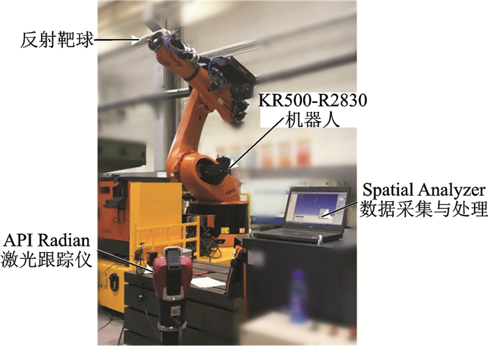
3 试验与结果分析 3.1 试验系统构建建立试验系统如图 3所示,主要包括KR500-R2830型机器人、API Radian激光跟踪仪及Spatial Analyzer数据采集与处理软件。设计试验方案,然后由激光跟踪仪对反射靶球进行测量,获取空间坐标点数据集,然后进行数据处理与分析,辨识运动学参数,进而完成精度补偿。

|
图 3 试验系统 Figure 3 Experiment system |
3.2 试验结果对比分析
为了对两步误差模型辨识方法进行验证,另外随机测量30个点,对未辨识参数前、误差模型同时辨识参数及两步误差模型辨识参数进行对比。由表 2可以看出,误差模型同时辨识参数法与两步误差模型辨识参数法对工业机器人精度提高明显,两步误差模型辨识参数法效果更好,且与误差模型同时辨识参数法用时相同。
| 表 2 不同情况下位置误差对比 Table 2 Comparison of position error in different situations |
3.3 案例验证
采用KR500-R2830型机器人,装载HSK高速电主轴,结合ROBOTMASTER离线编程,进行碳纤维薄板钻孔的加工。将基于两步误差模型方法辨识后的D-H参数替换机器人D-H参数,以补偿机器人的精度误差。通过对比分析加工前后的轮廓度、位置度的情况,给出结论。图 4为案例验证现场。进行碳纤维薄板钻孔的加工,测量不同孔的位置度,得出如表 3所示结果。从表 3可以发现,经过辨识与补偿后,机器人钻孔位置度由3 mm提高到1 mm以内。
| 表 3 精度优化前后对比 Table 3 Comparison of precision optimization(Before and after) |

|
图 4 案例验证 Figure 4 Case validation |
4 结束语
针对机器人运动学参数中位置与角度参数物理含义不同,同时进行位置与角度误差辨识存在精度丢失现象,通过建立正确的D-H模型,并采用所提出的两步误差模型进行运动学参数辨识。通过对比未进行参数辨识情况、误差模型同时参数辨识情况及两步误差模型参数辨识情况,验证了两步误差模型的正确性与有效性,并展现了其优势。将辨识的参数代入机器人控制系统中,机器人钻孔位置度由3 mm提高到1 mm以内。对于更高精度要求的应用场合,可以考虑重力、温度等因素及数据采集数量对所建模型的影响,以提高运动学参数辨识的准确性。
| [1] |
DEVLIEG R.
High-accuracy robotic drilling/milling of 737 inboard flaps[J]. SAE International Journal of Aerospace, 2011, 4: 1373–1379.
DOI:10.4271/2011-01-2733
|
| [2] |
毕云波, 李永超, 顾金伟, 等.
机器人自动化制孔系统[J]. 浙江大学学报:工学版, 2014, 48(8): 1427–1433.
BI Yunbo, LI Yongchao, GU Jinwei, et al. Robotic automatic drilling system[J]. Journal of Zhejiang University:Engineering Science, 2014, 48(8): 1427–1433. |
| [3] |
史晓佳, 张福民, 曲兴华, 等.
KUKA工业机器人位姿测量与在线误差补偿研究[J]. 机械工程学报, 2017, 53(8): 1–7.
SHI Xiaojia, ZHANG Fumin, QU Xinghua, et al. Position and attitude measurement and online errors compensation for KUKA industrial robots[J]. Chinese Journal of Mechanical Engineering, 2017, 53(8): 1–7. |
| [4] |
孙京, 刘金山, 赵长喜.
航天智能制造的思考与展望[J]. 航天器环境工程, 2015, 32(6): 577–582.
DOI:10.3969/j.issn.1673-1379.2015.06.002 SUN Jing, LIU Jingsan, ZHAO Changxi. A retrospective and prospective review of aerospace smart-manufacturing[J]. Spacecraft Environment Engineering, 2015, 32(6): 577–582. DOI:10.3969/j.issn.1673-1379.2015.06.002 |
| [5] |
RADZIWON A, BILBERG A, BOGERS M, et al.
The smart factory:Exploring adaptive and flexible manufacturing solutions[J]. Procedia Engineering, 2014, 69(1): 1184–1190.
|
| [6] |
ZENG Yuanfan, TIAN Wei, LI Dawei, et al.
An error-similarity-based robot positional accuracy improvement method for a robotic drilling and riveting system[J]. International Journal of Advanced Manufacturing Technology, 2017, 88(9/12): 2745–2755.
|
| [7] |
范明争, 韩先国.
基于标定及补偿提高串联机器人定位精度方法[J]. 北京航空航天大学学报, 2017, 43(1): 176–183.
FAN Mingzheng, HAN Xianguo. Precision improvement method for serial robot localization based on a new calibration and compensation strategy[J]. Journal of Beijing University of Aeronautics and Astronautics, 2017, 43(1): 176–183. |
| [8] |
高文斌, 王宏光, 姜勇, 等.
基于距离误差的机器人运动学参数标定方法[J]. 机器人, 2013, 35(5): 600–606.
GAO Wenbin, WANG Hongguang, JIANG Yong. Kinematic calibration method of robots based on distance error[J]. Robot, 2013, 35(5): 600–606. |
| [9] |
任永杰, 邾继贵, 杨学友, 等.
利用激光跟踪仪对机器人进行标定的方法[J]. 机械工程学报, 2007, 43(9): 195–200.
DOI:10.3321/j.issn:0577-6686.2007.09.038 REN Yongjie, ZHU Jigui, YANG Xueyou, et al. Method of robot calibration based on laser tracker[J]. Chinese Journal of Mechanical Engineering, 2007, 43(9): 195–200. DOI:10.3321/j.issn:0577-6686.2007.09.038 |
| [10] |
任永杰, 邾继贵, 杨学友, 等.
基于距离精度的测量机器人标定模型及算法[J]. 计量学报, 2008, 29(3): 198–202.
REN Yongjie, ZHU Jigui, YANG Xueyou, et al. Measurement robot calibration model and algorithm based on distance accuracy[J]. Acta Metrologica Sinica, 2008, 29(3): 198–202. |
| [11] |
美国自动精密工程公司.机器人校准[EB/OL].http://www.apisensor.com/cn, 2018-8-28.
|
| [12] |
叶声华, 王一, 任永杰, 等.
基于激光跟踪仪的机器人运动学参数标定方法[J]. 天津大学学报, 2007, 40(2): 202–205.
DOI:10.3969/j.issn.0493-2137.2007.02.014 YE Shenghua, WANG Yi, REN Yongjie. Calibration of robot kinematic parameters based on laser tracker[J]. Journal of Tianjin University, 2007, 40(2): 202–205. DOI:10.3969/j.issn.0493-2137.2007.02.014 |
 2018, Vol. 50


