随着现代科技的发展,微电子器件和微机电系统正高速地向微型化推进。微器件中广泛应用微/纳米尺度低维材料,如金属内连导线,以满足微系统高度集成化和高速微型化的要求。研究发现内连导线的应力失效速度与其尺寸效应密切相关[1-2]。因此,研究线宽对金属内连导线中微裂纹演化的影响具有重要的理论和工程应用价值。
数值模拟是应力诱发下微裂纹形态演化的主要研究方法[3-11]。Levitas等[12]对应力诱发表面扩散下微结构相变的现象提出了解析解并进行了有限元模拟。Ogurtani和Akyildiz[13]研究了在电迁移和热应力梯度作用下孔洞形貌演化。Shewmon[14]对于孔洞的研究结果表明在小尺寸微裂纹的演化过程中,表面扩散起主导作用。Pan等[15]研究发现表面张力与晶界张力的共同作用决定了多晶固体颗粒的表面形貌。
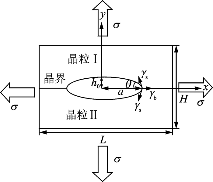
包含表面扩散和蒸发-凝结机制的仿真微结构演化的有限元方法首次由Sun和Suo[16]提出,He等[17-18]将此方法推广至外场诱发下微结构演化。本文沿用此方法,详细分析仅在表面扩散下线宽对内连导线中沿晶微裂纹演化的影响,且采用如图 1所示的模型。
|
图 1 内连导线中沿晶微裂纹模型 Figure 1 Simplified model of an intergranular microcrack in a conductor |
图 1所示为铜内连导线中沿晶微裂纹模型。假设铜内连导线发生理想弹性形变,垂直于平面的维度远远大于平面上的两个维度,则可将该问题简化为平面应变问题,其横截面即表示微裂纹的裂腔表面。裂纹形貌由形态比
在考虑形貌演化的因素时,不仅要考虑载荷引起的应力场作用,同时要兼顾晶体内部的表面能作用与晶界处的晶界能作用,并假设这三者的作用相互独立。此外,晶界与裂面相交处在表面能γs与晶界能γb共同作用下存在晶界热蚀沟现象,且2θ为晶界三叉点处的二面角(图 1)。
1 有限元方法 1.1 微结构演化的弱解描述当微结构表面同时存在表面扩散和蒸发-凝结两种质流过程时,表面扩散驱动力F与蒸发凝结驱动力p作用下系统自由能的减少量-δG为[16]
| $ \int_{{\rm{surface}}} {\boldsymbol{F} \cdot \delta \boldsymbol{I}} {\rm{d}}s + {\rm{ }}\int_{{\rm{surface}}} {\boldsymbol{p} \cdot \delta i} {\rm{d}}s = - \delta G $ | (1) |
式中:δI为表面扩散下的物质虚位移;δi为蒸发-凝结下的表面法向虚位移。
根据Herring理论[19],采用线性动力学原理
| $ \boldsymbol{J} = {\rm{ }}M\boldsymbol{F} $ | (2) |
| $ j = m\boldsymbol{p} $ | (3) |
式中:J为表面扩散的流量;j为蒸发-凝结下表面法向速度;M与m分别为表面扩散与蒸发-凝结的原子迁移率。
结合质量守恒定理,表面扩散与蒸发-凝结机制下的弱解描述为[16]
| $ \int \{\frac{{\boldsymbol{J}\delta \boldsymbol{I}}}{M} + \frac{{\left( {{\boldsymbol{v}_n} + {\rm{ }}\partial \boldsymbol{J}\partial s{\rm{ }}} \right)\left[ {\delta {\boldsymbol{r}_n} + {\rm{ }}\partial \left( {\delta \boldsymbol{I}} \right)/\partial s} \right]{\rm{ }}}}{m}\} {\rm{d}}s = - \delta G $ | (4) |
式中vn和δrn分别为两种机制下的微结构表面的真实法向速度和表面法向虚位移。
1.2 系统自由能在一般情况下,微结构系统的总自由能由多个部分组成,如表面能、晶界能、化学能以及弹性能等。在图 1所示的模型中,假定机械载荷仅体现为对位移的控制,而不存在载荷对表面演变过程的作用;且系统的总自由能仅包括表面能、晶界能和应变能,即
| $ G = \int_{{\rm{surface}}} {{\gamma _{\rm{s}}}} {\rm{d}}A + {\rm{ }}\int_{{\rm{grain}}\;{\rm{boundary}}} {{\gamma _{\rm{b}}}} {\rm{d}}A + \int_{{\rm{volume}}} w {\rm{d}}v $ | (5) |
式中w为应变能密度。由于微裂纹形态演化过程比较快,所以假定固体在微裂纹演化过程中始终处于机械平衡状态。因而可确定在任何时刻、任何给定的表面构形下的系统应力场以及相应的应变能密度。
1.3 有限单元法二维沿晶微裂纹的表面可用许多线性单元来拟合。单元节点的坐标及物质位移I形成广义坐标qi,广义速度为
| $ \delta G = - \sum {{f_i}\delta {q_i}} $ | (6) |
式中fi为广义力。两端消去δqi后可得
| $ \sum\limits_j {{H_{ij}} \cdot {{\dot q}_j}} = {f_i} $ | (7) |
式中Hij为粘度矩阵中的变量。
基于以上控制方程,如给定当前构形的沿晶微裂纹,使用当前的广义坐标计算式中的粘度矩阵H以及载荷向量f,通过Gauss-Seidel迭代求解式(7),得出各节点的广义速度为
在如图 1所示的晶界与裂面的三叉点处必须满足边界条件
| $ \cos \theta = \frac{{{\gamma _{\rm{b}}}}}{{2{\gamma _{\rm{s}}}}} $ | (8) |
由于沿晶微裂纹模型以及施加的电场关于x轴对称,第1个节点和第NG个节点处原子流量和y轴方向速率均为零,即
| $ {J_1} = {J_{NG}} = 0 $ | (9) |
| $ {{\dot y}_1} = {{\dot y}_{NG}} = 0 $ | (10) |
基于所建立的有限单元控制方程,采用六节点三角形单元,应用Fortran语言编制相应程序,数值分析双向等值拉应力诱发表面扩散下铜内椭圆形沿晶微裂纹的演化规律。仅在表面扩散下的微裂纹在形态演化过程中其腔体的总体积应保持为常数。计算结果表明本文计算精度可靠。为便于计算,采用量纲一化应力
图 2分别给出了

|
图 2 |
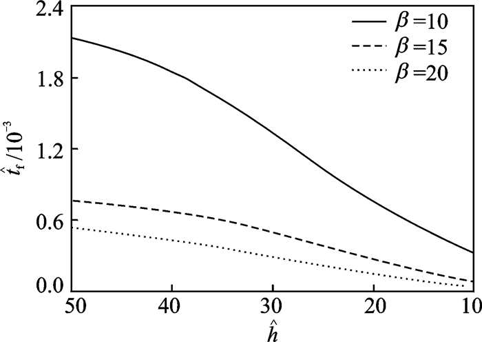
对比图 2(c, e)可见,随着线宽的减小,分节时左右两个裂腔将增大,同时分节所需的时间将减小。图 3详细给出了
|
图 3 分节时间 |
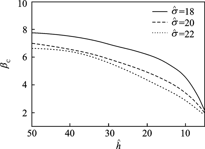
通过大量的数值计算可知:对于给定形态比与外载下的沿晶微裂纹,存在一个临界线宽
|
图 4 临界形态比βc与线宽 |
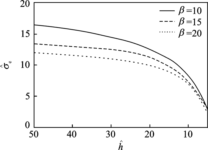
给定形态比和线宽,沿晶微裂纹存在形态演化分叉的临界外载
|
图 5 临界外载 |
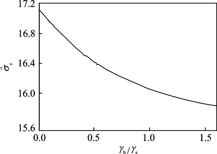
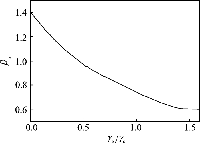
晶界的存在是沿晶微裂纹与晶内微裂纹物理性质差异的关键,其对于微裂纹的演化存在着不可忽略的影响。图 6,7分别给出了形态比β=10和外载σ=20时临界外载
|
图 6 临界外载 |
|
图 7 临界形态比βc随γb/γs的变化 Figure 7 Critical value of aspect ratio βc as a function of γb/γs |
3 结论
本文应用有限单元法数值模拟了内连导线线宽对沿晶微裂纹演化的影响,得出具体结论如下:
(1) 对于给定形态比与外载下的沿晶微裂纹,存在一个临界线宽
(2) 沿晶微裂纹分节时间随着线宽的减小而减小,即减小线宽可以加速微裂纹分节。
(3) 临界外载与临界形态比都随着线宽的减小而减小,即,减小线宽有利于微裂纹分节。且当
(4) 临界外载、临界形态比随着晶界能与表面能比值的增大而减小,且沿晶微裂纹比晶内微裂纹更易发生分节。
由于内连导线中微裂纹发生分节形成的小裂纹不足以使得内连导线产生断路,从而保持电路的稳定;反之,内连导线中微裂纹的扩展会导致导线断裂,造成电路失效。本文模拟结果可为内连导线的寿命预测和安全设计的准则提供理论依据和技术支持。
| [1] | KORHONEN M A, PASZKIET C A, LI C Y. Mechanisms of thermal stress relaxation and stress induced voiding in narrow aluminium-based metallizations[J]. Journal of Applied Physics, 1991, 69(12): 8083–8091. DOI:10.1063/1.347457 |
| [2] | ZHAI C J, WALTER Y H, MARATHE A P, et al. Simulation and experiments of stress migration for Cu/low-k BEoL[J]. IEEE Transactions on Device and Materials Reliability, 2004, 4(3): 523–529. DOI:10.1109/TDMR.2004.833225 |
| [3] | HULL D, RIMMER D E. The growth of grain-boundary voids under stress[J]. Philosophical Magazine, 1959, 4(42): 673–687. DOI:10.1080/14786435908243264 |
| [4] | RAJ R, ASHBY M F. Intergranular fracture at elevated temperature[J]. Acta Metallurgica, 1975, 23(6): 653–666. DOI:10.1016/0001-6160(75)90047-4 |
| [5] | CHUANG T E, RICE J R. The shape of intergranular creep cracks growing by surface diffusion[J]. Acta Metallurgica, 1973, 21(12): 1625–1628. DOI:10.1016/0001-6160(73)90105-3 |
| [6] | PREVOST J H, BAKER T J, LIANG J, et al. A finite element method for stress-assisted surface reaction and delayed fracture[J]. International Journal of Solids and Structures, 2001, 38(30/31): 5185–5203. |
| [7] | LIU Z, YU H. A numerical study on the effect of mobilities and initial profile in thin film morphology evolution[J]. Thin Solid Films, 2006, 513(1/2): 391–398. |
| [8] | BOWER A F, SHANKAR S. A finite element model of electromigration induced void nucleation, growth and evolution in interconnects[J]. Modelling and Simulation in Materials Science and Engineering, 2007, 15(8): 923. DOI:10.1088/0965-0393/15/8/008 |
| [9] | LIU Z, YU H. Stress relaxation of thin film due to coupled surface and grain boundary diffusion[J]. Thin Solid Films, 2010, 518(20): 5777–5785. DOI:10.1016/j.tsf.2010.05.079 |
| [10] | SINGH N, BOWER A F, SHANKAR S. A three-dimensional model of electro migration and stress induced void nucleation in interconnect structures[J]. Modelling and Simulation in Materials Science and Engineering, 2010, 18(6): 65006. DOI:10.1088/0965-0393/18/6/065006 |
| [11] | HUANG P Z, ZHANG Z Z, GUO J W, et al. Axisymmetric finite-element analysis for interface migration-controlled shape instabilities of plate-like double-crystal grains[J]. Advanced Materials Research, 2012, 460: 230–235. DOI:10.4028/www.scientific.net/AMR.460 |
| [12] | LEVITAS V I, LEE D, PRESTON D L. Interface propagation and microstructure evolution in phase field models of stress-induced martensitic phase transformations[J]. International Journal of Plasticity, 2010, 26(3): 395–422. DOI:10.1016/j.ijplas.2009.08.003 |
| [13] | OGURTANI T O, AK YILDIZ O. Cathode edge displacement by voiding coupled with grain boundary grooving in bamboo like metallic interconnects by surface drift-diffusion under the capillary and electromigration forces[J]. International Journal of Solids and Structures, 2008, 45(3/4): 921–942. |
| [14] | SHEWMON P G. The movement of small inclusions in solids by a temperature gradient[J]. Transactions of the Metallurgical Society of AIME, 1964, 230(4): 1134–1137. |
| [15] | PAN J, COCKS A. A numerical technique for the analysis of coupled surface and grain-boundary diffusion[J]. Acta Metal Mater, 1995, 43(4): 1395–1406. DOI:10.1016/0956-7151(94)00365-O |
| [16] | SUN B, SUO Z. A finite element method for simulating interface motion—Ⅱ. Large shape change due to surface diffusion[J]. Acta Metallurgica, 1997, 45(12): 4963–4962. |
| [17] | HE D N, HUANG P Z. A finite-element analysis of intragranular microcracks in metal interconnects due to surface diffusion induced by stress migration[J]. Computational Materials Science, 2014, 87: 65–71. DOI:10.1016/j.commatsci.2014.01.063 |
| [18] | HE D N, HUANG P Z. A finite-element analysis of in-grain microcracks caused by surface diffusion induced by electromigration[J]. International Journal of Solids and Structures, 2015, 62: 248–255. DOI:10.1016/j.ijsolstr.2015.02.039 |
| [19] | HERRING C. Surface tension as a motivation for sintering[C]//The Physics of Powder Metallurgy. New York: McGraw-Hill, 1951:33-69.http://link.springer.com/chapter/10.1007/978-3-642-59938-5_2 |
 2017, Vol. 49


