随着齿轮传动功率密度、可靠性等要求的提高以及新型材料、齿面硬化等技术的应用,齿轮接触疲劳问题愈加突出。传统齿轮接触疲劳寿命基于赫兹接触理论求解齿面压力,采用经验公式计算,没有专门考虑润滑因素的影响。而齿轮在高速重载下的弹流润滑效应十分明显,在全膜润滑下油膜压力分布与赫兹压力不同,表层应力场也不同;尤其二次压力峰的大小、位置以及颈缩造成的应力集中直接影响接触疲劳寿命。开展弹流润滑情况下齿轮接触疲劳研究,对提高齿轮疲劳寿命具有重要意义。
针对弹流润滑状态下的齿轮接触疲劳寿命,朱东等人构建三维线接触混合润滑模型,采用Von Mises应力和Zaretsky疲劳寿命模型预测点蚀疲劳寿命[1];Li等人用特征面法多轴疲劳模型预测齿轮裂纹萌生寿命[2];Evans等人基于微弹流分析和疲劳损伤累积理论研究了斜齿轮点蚀疲劳问题[3];Seabra等人研究齿轮微点蚀问题时考虑了齿面接触疲劳与齿面磨损的综合作用[4];王文中等人采用Von Mises等效应力和Zaretsky寿命模型预测了弹流润滑状态下斜齿轮的接触疲劳寿命[5]。朱才朝等人研究了斜齿轮的有限长热弹流润滑问题[6-7];刘怀举等人研究了直齿轮动载荷下的弹流润滑问题[8];孙章栋等人研究了摆线针轮热弹流润及乏油问题[9]。本文基于渐开线直齿轮弹流润滑接触分析模型,利用DC-FFT算法求解次表面应力场,结合临界平面法研究接触疲劳问题,探讨弹流润滑下次表面应力与疲劳寿命关联规律。
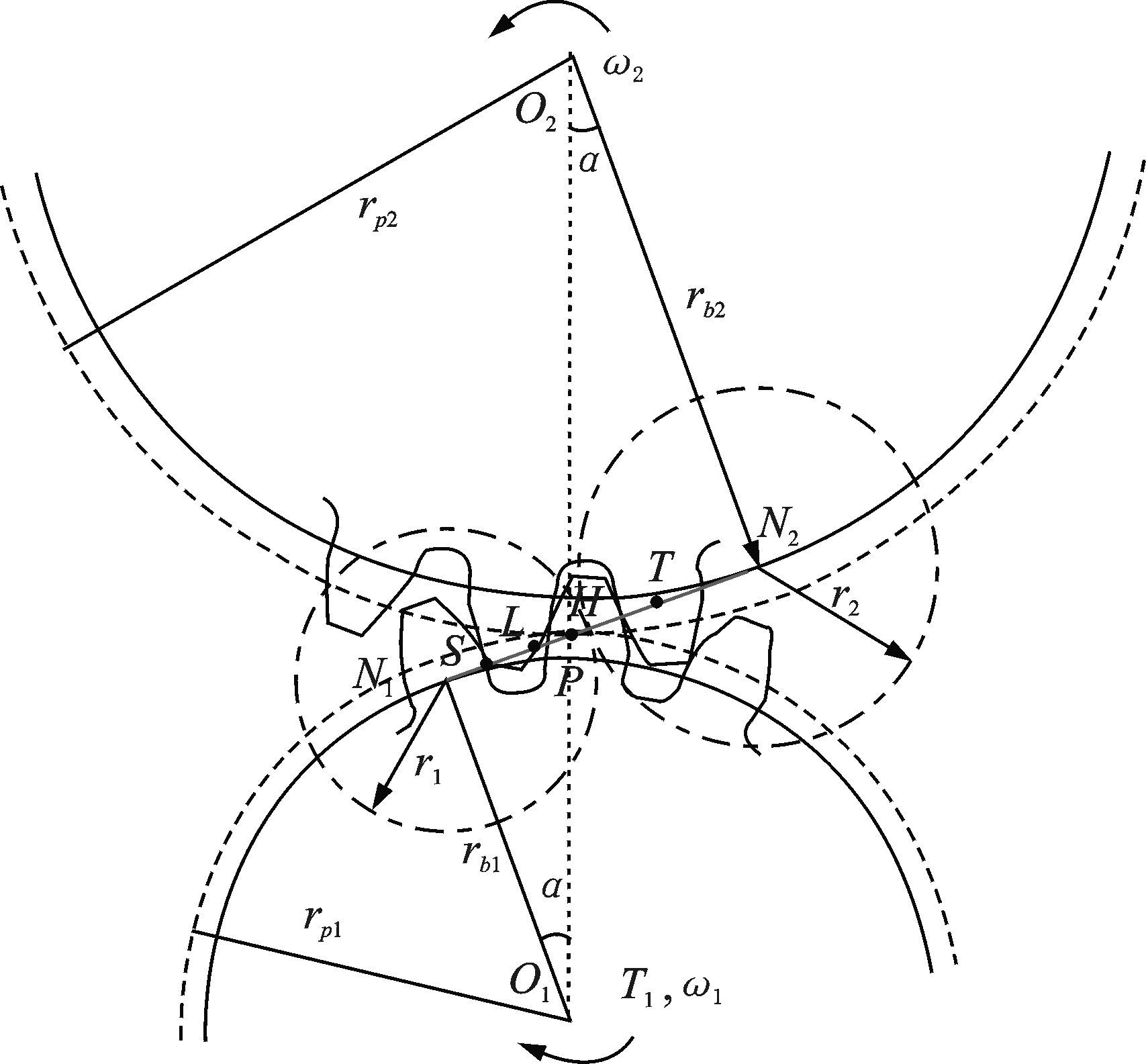
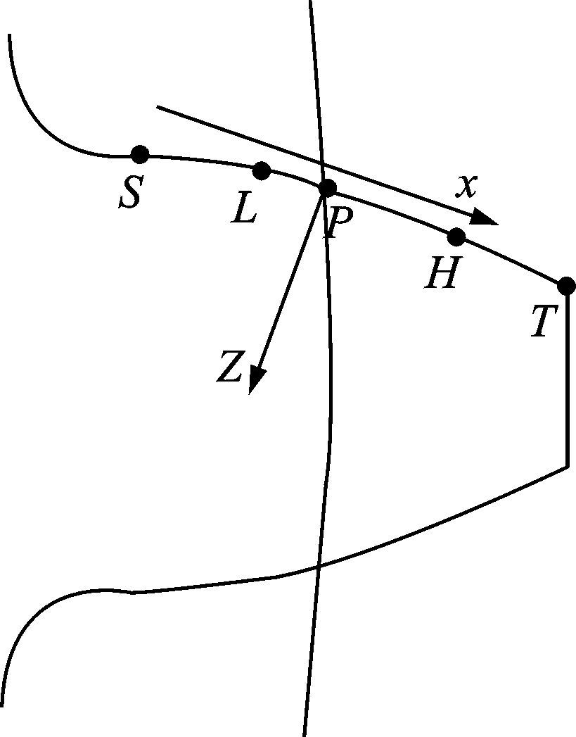
1 弹流润滑接触建模 1.1 直齿轮啮合过程分析渐开线直齿轮副在啮合过程中会经历单双齿交替啮合的过程,如图 1所示。N1N2为理论啮合线,一对轮齿由实际啮合线起点S啮入,在L点进入单齿啮合区,经过节点P从H点脱离单齿啮合区,在T点啮出。其中SL和HT为双齿啮合区,SH=LT=pb,pb为基圆齿距。在L和H点经历单双齿啮合的变化,将瞬变前后分别记为AL、BL和AH、BH。将啮合过程投影到小齿轮(主动轮)一个齿廓上,以节点P为原点,沿啮合线方向为x轴、垂直齿面方向为z轴建立坐标系,如图 2所示,啮合线上5个特殊点的横坐标如下
| $\left\{ \begin{align} & {{x}_{S}}=-\left( \sqrt{{{r}_{a2}}^{2}-{{r}_{b2}}^{2}}-{{r}_{p2}}sin\alpha \right) \\ & {{x}_{L}}=-\left( {{r}_{p1}}sin\alpha +{{p}_{b}}-\sqrt{{{r}_{a1}}^{2}-{{r}_{b1}}^{2}} \right) \\ & {{x}_{P}}=0 \\ & {{x}_{H}}={{r}_{p2}}sin\alpha +{{p}_{b}}-\sqrt{{{r}_{a2}}^{2}-{{r}_{b2}}^{2}} \\ & {{x}_{T}}=\sqrt{{{r}_{a1}}^{2}-{{r}_{b1}}^{2}}-{{r}_{p1}}sin\alpha \\ \end{align} \right.$ |
其中:rai、rbi、rpi分别为齿轮i(i=1,2)的齿顶圆、齿根圆和节圆半径;α为节圆压力角。
|
图 1 直齿轮副啮合过程 Figure 1 Meshing process of spur gear |
|
图 2 主动齿轮坐标系 Figure 2 Coordinate system of driving gear |
在啮合过程中,齿轮接触曲率半径、卷吸速度、齿间啮合力均是时变量。当接触宽度远小于啮合点处的曲率半径时,在每个啮合点处都可用两个当量圆柱来代替齿轮副的接触[10],渐开线直齿轮啮合过程中的时变接触曲率半径和滚动速度为[11]
| $\left\{ \begin{align} & r=\frac{{{r}_{1}}{{r}_{2}}}{{{r}_{1}}+{{r}_{2}}} \\ & {{u}_{1,2}}={{\omega }_{1,2}}\times {{r}_{1,2}} \\ & {{u}_{r}}=\frac{{{u}_{1}}+{{u}_{2}}}{2} \\ & SR=\frac{{{u}_{1}}-{{u}_{2}}}{{{u}_{r}}}~ \\ \end{align} \right.$ | (1) |
式中:ri、ui和ωi分别为齿轮i(i=1,2)在啮合点处的接触曲率半径、表面速度和转速;r为齿轮副当量曲率半径;ur为齿面平均速度;SR为滑滚比。单位齿宽载荷由载荷分配系数计算[12],单位齿宽载荷F由载荷分配系数S(ξ)表示
| $F=\frac{{{T}_{1}}}{{{b}_{w}}}S\left( \xi \right)$ | (2) |
式中:ξ为啮合点坐标;bw为齿宽。
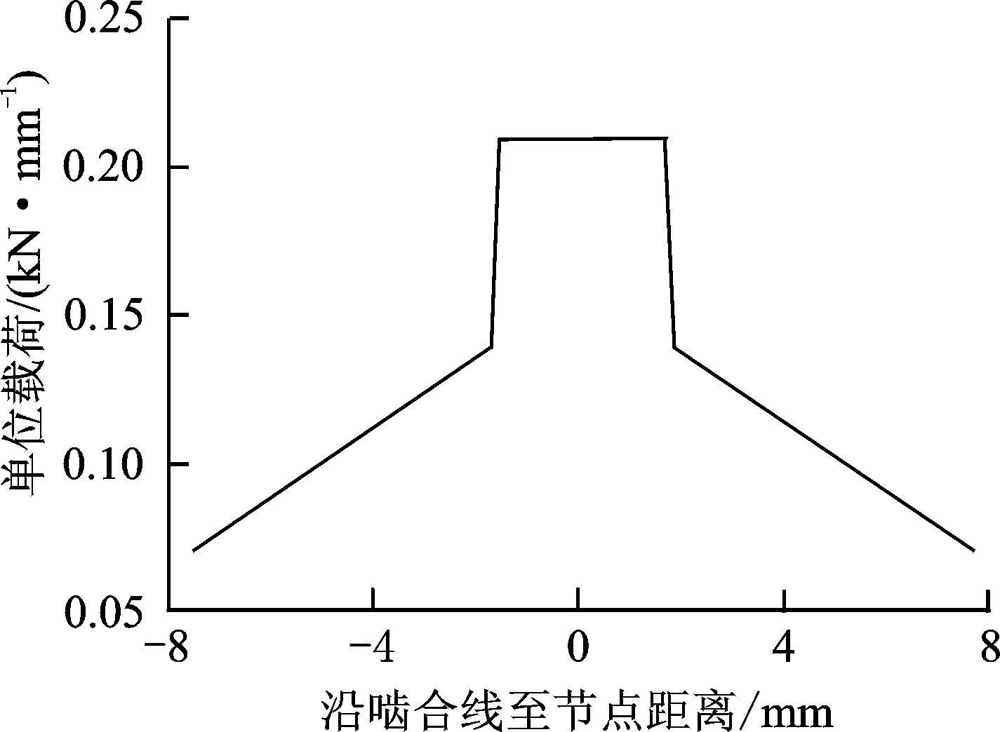
| $S\xi =\left\{ \begin{matrix} \frac{1}{3}(1+\frac{\xi -{{x}_{S}}}{{{x}_{L}}-{{x}_{S}}})\text{ } & {{x}_{S}}\le \xi \le {{x}_{L}} \\ 1 & {{x}_{L}}\le \xi \le {{x}_{H}} \\ \frac{1}{3}(1-\frac{\xi -{{x}_{T}}}{{{x}_{T}}-{{x}_{H}}}) & {{x}_{H}}\le \xi \le {{x}_{T}} \\ \end{matrix} \right.$ | (3) |
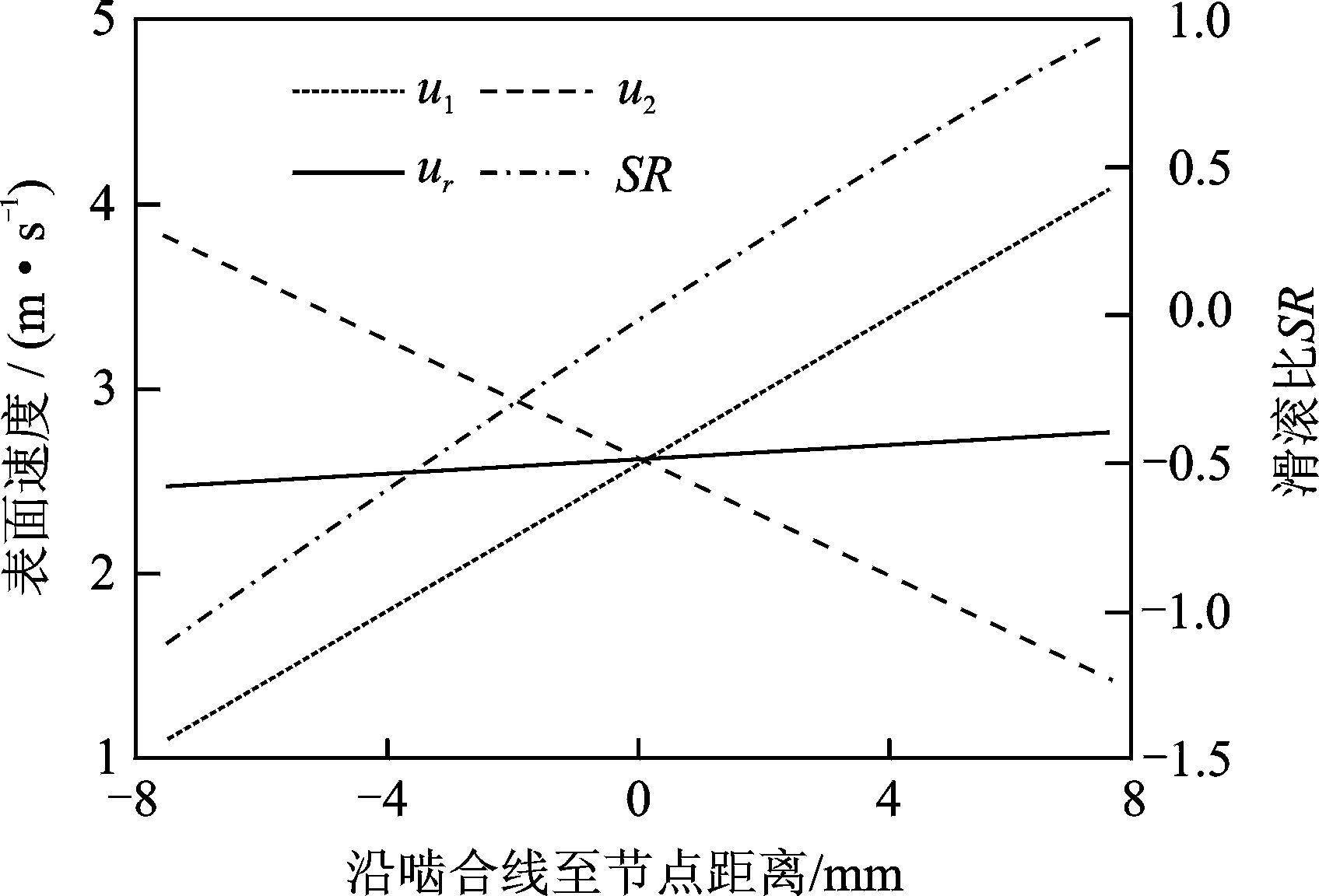
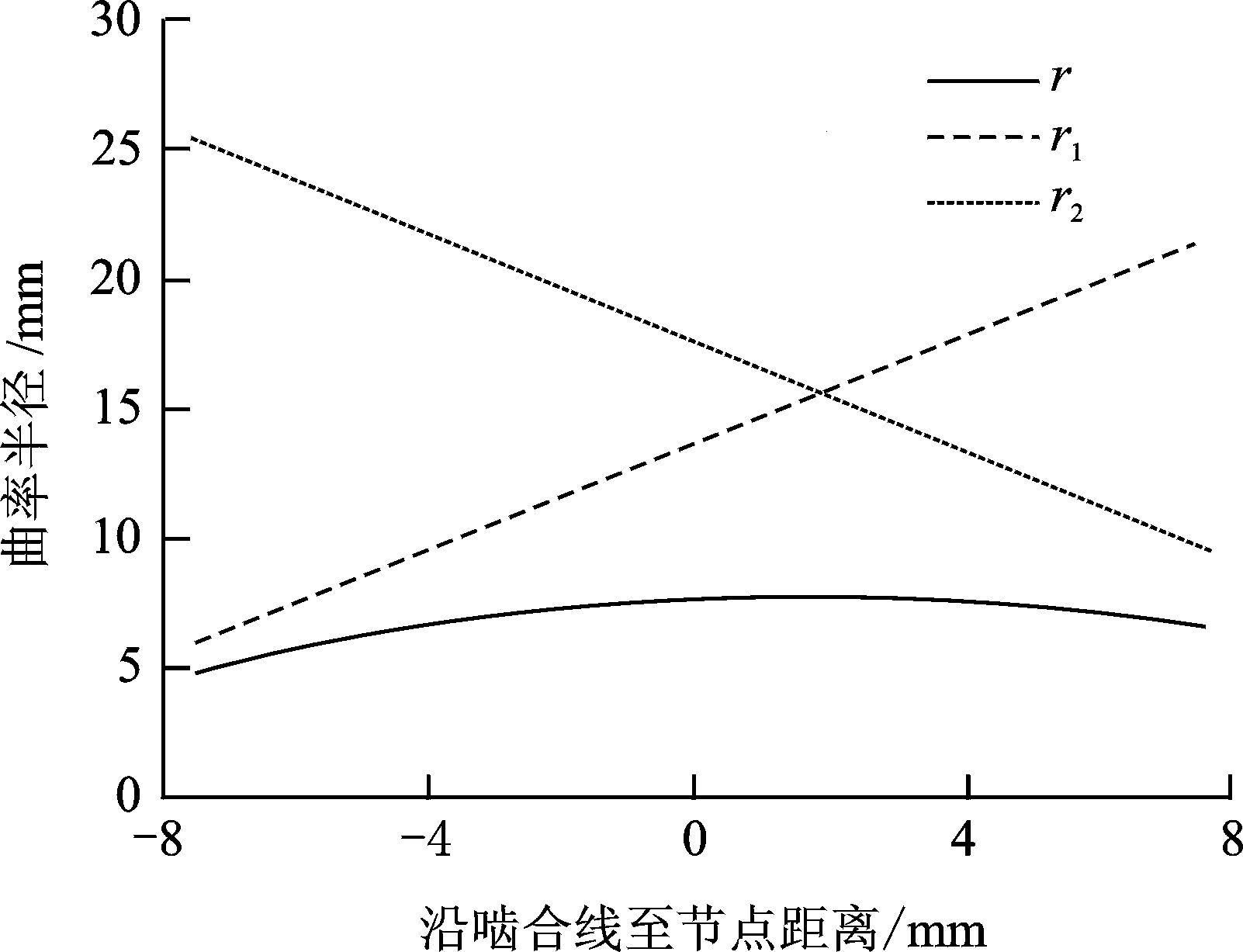
齿轮参数如表 1所示,齿轮材料采用20MnCr5。小齿轮1为主动轮,齿面速度与滑滚比如图 3所示。在节点处u1=u2=ur,此时滑滚比为0,在节点前后由负值变为正值。齿轮副在啮合点处的曲率半径沿啮合线分布如图 4所示,r1、r2随时间呈线性变化,当量曲率半径r先逐渐增大,在r1=r2=2r达到最大值。
| 表 1 齿轮参数 Table 1 Gear parameters |
|
图 3 滚动速度沿啮合线变化 Figure 3 Change of rolling velocity along line of action |
|
图 4 曲率半径沿啮合线变化 Figure 4 Change of curvature radius along line of action |
图 5为单位齿宽载荷沿啮合线的分布,由于在双齿啮合区由两对轮齿共同分担载荷,在此区域起止点处单位齿宽载荷分别约为单齿区的1/3和2/3。图 6为最大赫兹接触压力和接触半宽沿啮合线的变化,与单位齿宽载荷对应,在单双齿交替时经历突变,啮合线上的特殊点位置如图 6所示。最大赫兹接触应力在单齿啮合最低点(即BL点)达到最大,且节点以下部分大于节点以上部分,符合齿轮接触疲劳最先发生在节线以下靠近齿根区域的结论。
|
图 5 单位线宽载荷沿啮合线变化 Figure 5 Change of meshing force along line of action |

|
图 6 赫兹压力和赫兹半宽沿啮合线变化 Figure 6 Change of Hertz stress and half-width along line of action |
1.2 弹流润滑分析
直齿轮润滑模型可简化为一维线接触等温弹流润滑问题的求解,简化后的一维Reynolds方程为
| $\frac{d}{dx}\left( \frac{\rho {{h}^{3}}}{\eta }\frac{dp}{dx} \right)=12{{u}_{e}}\frac{d\rho }{dx}$ | (4) |
式中:ρ和η分别为润滑油密度和黏度;ue为齿面平均速度;x为沿接触方向的坐标;p和h分别为压力和膜厚。
膜厚方程
| $h\left( x \right)={{h}_{0}}+\frac{{{x}^{2}}}{2r}+def\left( x \right)$ | (5) |
式中:h0为光滑表面中央膜厚;def(x)为表面弹性变形,由式(6) 计算
| $def\left( x \right)=-\frac{2}{\pi E}\int_{-\infty }^{x*}{p\left( s \right)}\ln {{\left( x-s \right)}^{2}}ds$ | (6) |
载荷平衡方程
| $w=\int_{-\infty }^{x*}{pdx}$ | (7) |
密压方程
| $\rho ={{\rho }_{0}}\frac{0.59\times {{10}^{9}}+1.34p}{0.59\times {{10}^{9}}+p}$ | (8) |
黏压方程
| $\eta ={{\eta }_{0}}\exp \left\{ \left( \ln {{\eta }_{0}}+9.67 \right)\left[ -1+{{\left( 1+\frac{p}{{{p}_{0}}} \right)}^{z}} \right] \right\}$ | (9) |
将以上方程量纲一化,用线松弛迭代法求解压力和膜厚,量纲一量和量纲一参数如下
| $X=\frac{x}{b},P=\frac{p}{{{p}_{H}}},H=\frac{hr}{{{b}^{2}}},\bar{\eta }=\frac{\eta }{{{\eta }_{0}}},\bar{\rho }=\frac{\rho }{{{\rho }_{0}}}$ |
其中:η0为大气压下的黏度系数;p0为压力系数;b为赫兹接触半宽;pH为最大赫兹压力。
2 次表面应力场齿轮接触区尺寸远小于接触体表面曲率半径,用弹性半空间理论求解在齿面压力和剪切力作用下产生的次表面应力场[13]。假设流体为牛顿流体,齿面剪切力按库伦摩擦力计算,摩擦因数μ=0.1,则剪切力由式(10) 求解为
| $q\left( x,t \right)=\mu \times p\left( x,t \right)$ | (10) |
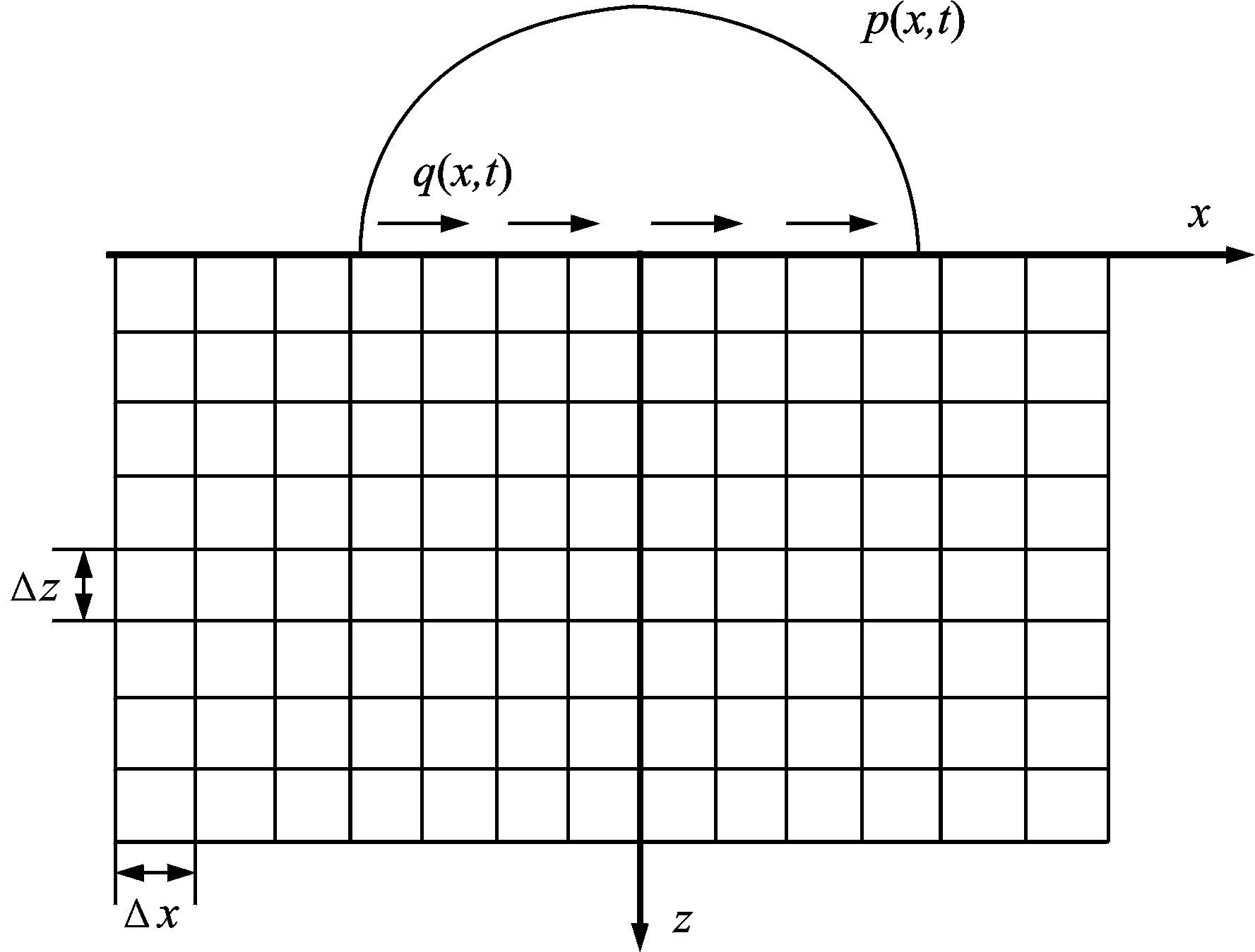
次表面应力分量σx,σz,τxz可由式(11) 计算,计算区域为-2.0bmax≤x≤2.0bmax,0≤z≤2.0bmax,将其划分为Nx×Nz个节点,如图 7所示。将方程离散为影响系数函数和压力相乘的形式,采用DC-FFT快速算法求解[14]。
| $\left\{ \begin{align} & {{\sigma }_{x}}\left( x,z,t \right)=-\frac{2z}{\pi }\int_{{{x}_{1}}}^{{{x}_{2}}}{\frac{p\left( s,t \right){{\left( x-s \right)}^{2}}ds}{{{[{{\left( x-s \right)}^{2}}+{{z}^{2}}]}^{2}}}}- \\ & 2\pi \int_{{{x}_{1}}}^{{{x}_{2}}}{\frac{p\left( s,t \right){{\left( x-s \right)}^{3}}ds}{{{[{{\left( x-s \right)}^{2}}+{{z}^{2}}]}^{2}}}} \\ & {{\sigma }_{z}}\left( x,z,t \right)=-\frac{2{{z}^{3}}}{\pi }\int_{{{x}_{1}}}^{{{x}_{2}}}{\frac{p\left( s,t \right)ds}{{{[{{\left( x-s \right)}^{2}}+{{z}^{2}}]}^{2}}}}- \\ & \frac{2{{z}^{2}}}{\pi }\int_{{{x}_{1}}}^{{{x}_{2}}}{\frac{p\left( s,t \right)\left( x-s \right)ds}{{{[{{\left( x-s \right)}^{2}}+{{z}^{2}}]}^{2}}}} \\ & {{\tau }_{xz}}\left( x,z,t \right)=-\frac{2{{z}^{2}}}{\pi }\int_{{{x}_{1}}}^{{{x}_{2}}}{\frac{p\left( s,t \right)\left( x-s \right)ds}{{{[{{\left( x-s \right)}^{2}}+{{z}^{2}}]}^{2}}}}- \\ & \frac{2{{z}^{2}}}{\pi }\int_{{{x}_{1}}}^{{{x}_{2}}}{\frac{p\left( s,t \right){{\left( x-s \right)}^{2}}ds}{{{[{{\left( x-s \right)}^{2}}+{{z}^{2}}]}^{2}}}} \\ \end{align} \right.$ | (11) |
|
图 7 应力场计算域 Figure 7 Calculation regions of stress field |
为探讨齿轮副啮合过程中应力场的时变特征,建立应力场时间序列[15],以实际啮合线起始点为原点建立oxz坐标系,其与oxz坐标系有如下转换关系
| $X={{x}_{offset}}+x-ut,Z=z$ | (12) |
式中:xoffset为t=0时oxz坐标系的位置;u为齿轮表面速度;通过坐标变换可以得到oxz坐标系中的应力场时间序列。
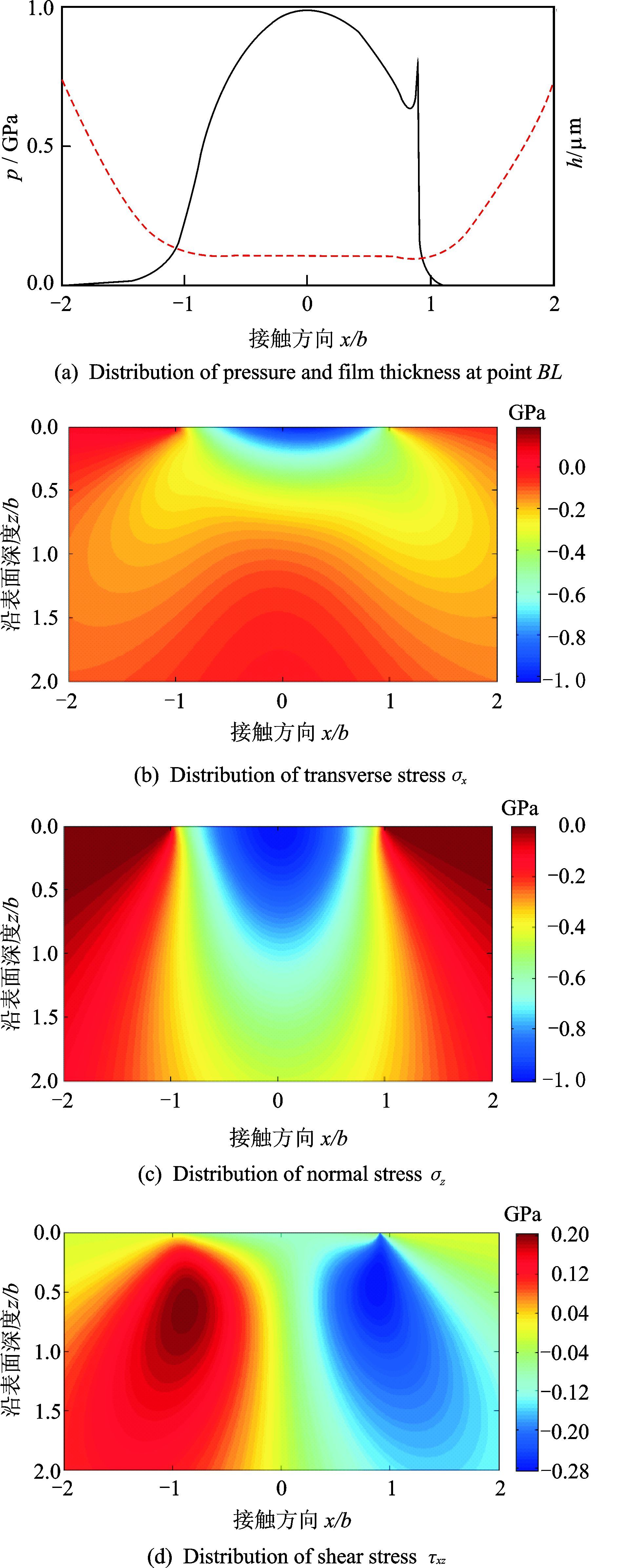
齿轮在BL点(x=-1.57 mm)单位齿宽载荷为F=0.21 kN/mm,最大赫兹压力为pH=1.01 GPa。弹流润滑齿面压力及次表面应力场如图 8所示,图 8(a)为弹流润滑下齿面压力和膜厚,出口区有明显的颈缩现象及二次压力峰,正交剪应力明显上移,且在表面附近开始产生应力集中。由图 8(b,c)可见齿轮次表面法向力为压应力,且在靠近表面位置取得最大值;图 8(d)显示次表面剪应力为交变应力,在光滑表面赫兹干接触情况下,剪应力在x=±0.85b,z=0.5b处取得极值τxz=0.25pH,由于二次压力峰和表面摩擦力的影响,极值位置上移且高于0.25pH。
|
图 8 弹流润滑齿面压力及次表面应力场 Figure 8 Distribution of pressure and stress |
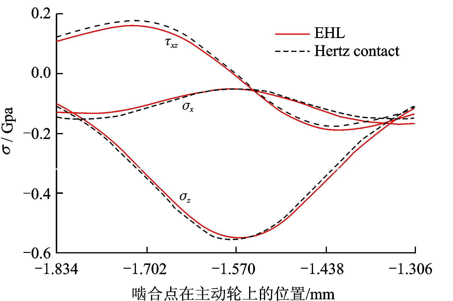
图 9为BL点z=0.5b处应力时间历程对比。在一个啮合过程中啮合点位于BL点时其次表面承受最大正应力,远离BL点时正应力接近于0,压应力为脉动循环应力;次表面剪应力为正交循环应力,其幅值为2τxz大于最大主剪应力。
|
图 9 BL点弹流润滑和赫兹干接触在z=0.5b处应力场时间历程 Figure 9 Stress history under EHL and Hertz dry contact at point BL in depth of z=0.5b |
3 接触疲劳分析 3.1 临界平面准则
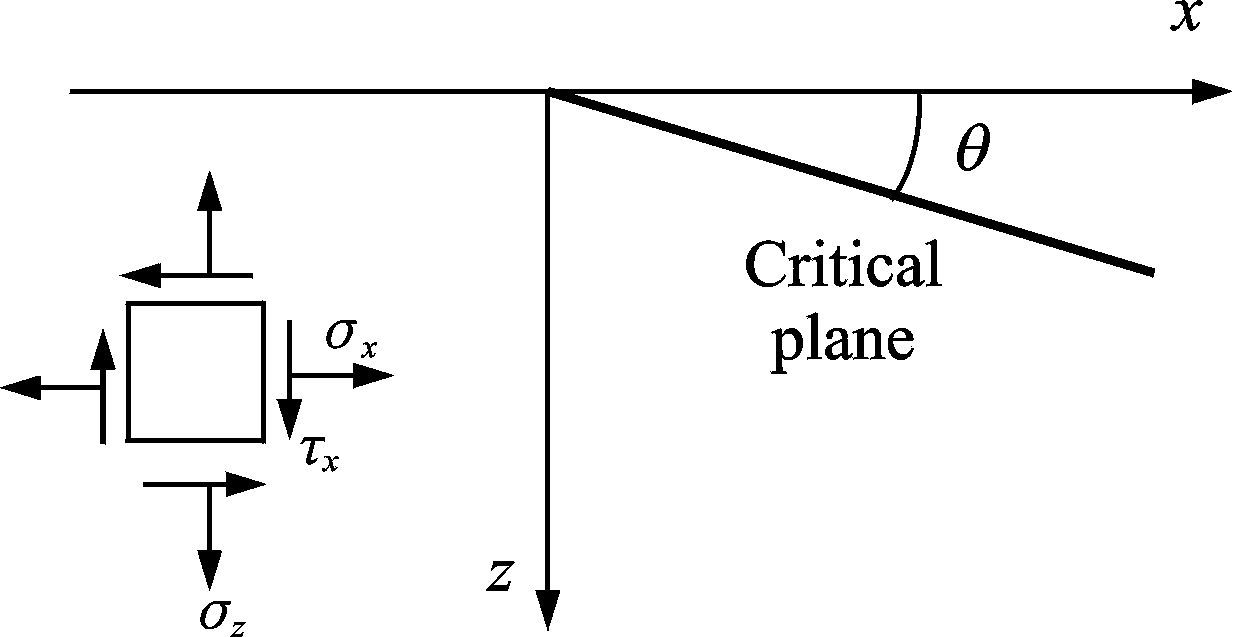
齿轮表面和次表面呈现复杂应力状态,且接触疲劳寿命通常能达到106以上,可采用多轴高周疲劳模型对齿轮接触疲劳寿命进行分析。本文采用临界平面疲劳分析模型研究齿轮接触疲劳寿命,其参数是临界平面夹角θ的函数[16],如图 10所示。
|
图 10 临界平面位置 Figure 10 Location of critical plane |
目前应用较广的临界平面准则有Matake准则和DangVan准则。Matake[17]准则假设临界平面是最大交变剪应力幅的平面,其疲劳参数为
| $FP\left( \theta ,t \right)=\frac{{{\tau }_{a}}({{\theta }_{c}},t)+\rho \cdot \sigma max({{\theta }_{c}},t)}{\lambda }$ | (13) |
式中:τa(θc,t)为临界面上交变剪应力幅值;σmax(θc,t)为次表面上的最大正应力;ρ和λ为材料参数,在Matake准则中取值为
| $\rho =\frac{2{{\tau }_{-1}}}{{{\sigma }_{-1}}}-1,\lambda ={{\tau }_{-1}}$ | (14) |
式中σ-1和τ-1分别为材料的拉压对称循环极限和扭转对称循环极限。DangVan[18]准则认为疲劳裂纹的萌生是由于材料内部的临界体积内特征滑移带上晶粒所受的塑形应变引起,其疲劳参数为
| $FP\left( \theta ,t \right)=\frac{{{\tau }_{m}}({{\theta }_{c}},t)+\rho \cdot {{\sigma }_{H}}\left( t \right)}{\lambda }$ | (15) |
式中:τm(θc,t)为临界面上最大剪应力值;σH(t)为静水应力。材料参数ρ和λ的取值为
| $\rho =\frac{3{{\tau }_{-1}}}{{{\sigma }_{-1}}}-\frac{3}{2},\lambda ={{\tau }_{-1}}$ | (16) |
对于齿轮材料,扭转对称循环极限与拉压对称循环极限的比值s=τ-1/σ-1为一个常数,取s值为0.64[19]。将材料参数代入临界平面准则中,此时的扭转对称循环疲劳极限变为循环次数为Nf时对应的等效切应力[20]。
| $\begin{align} & ma{{x}_{t}}\left( {{\tau }_{m}}\left( {{\theta }_{c}},t \right)+\left( 3s-3/2 \right)\text{ }{{\sigma }_{H}}\left( t \right) \right)= \\ & {{\tau }_{-1}}\cdot FP={{\tau }_{{{N}_{f}}}} \\ \end{align}$ | (17) |
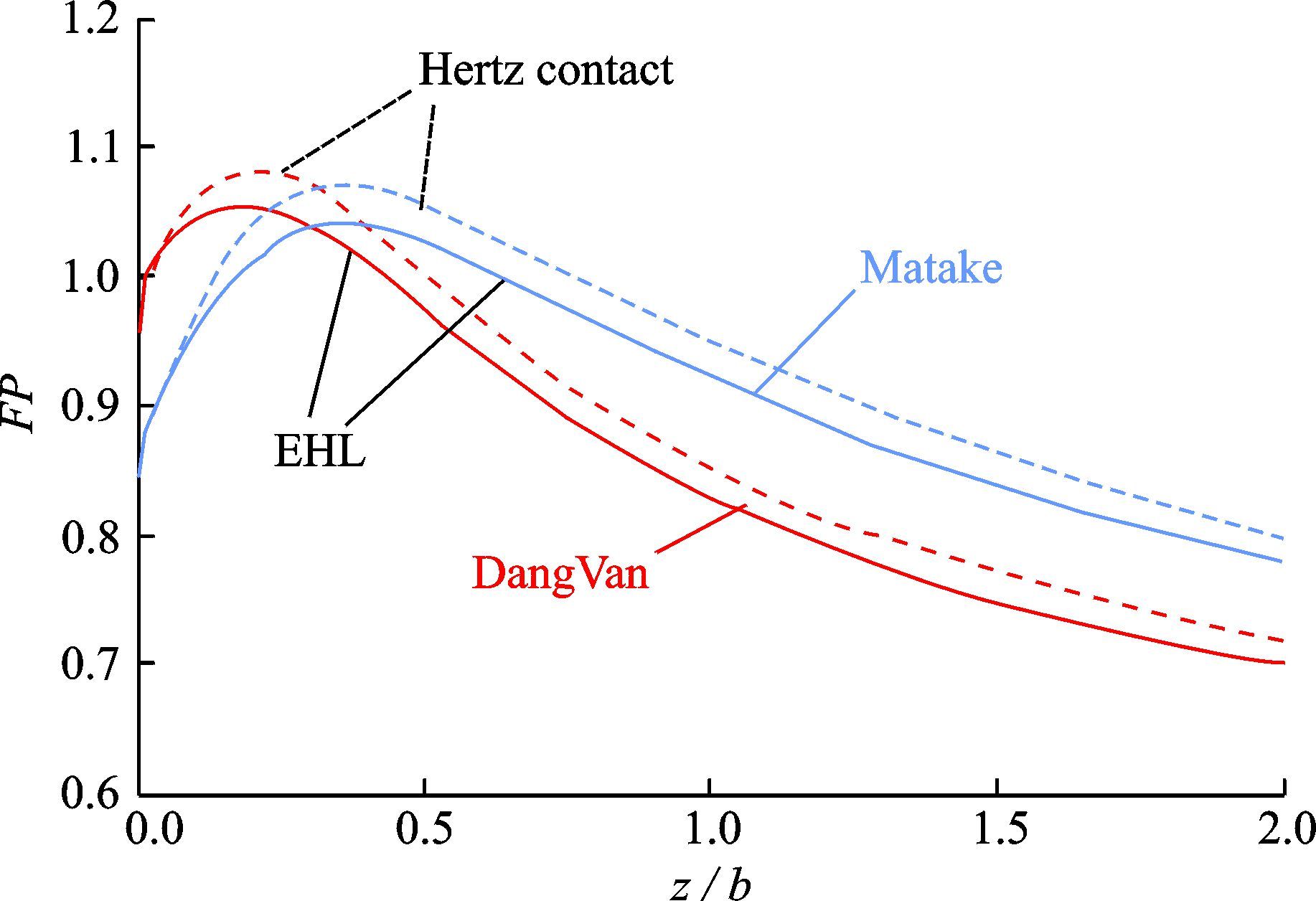
根据求解出齿轮次表面的多轴应力场,结合临界平面准则以及材料参数,计算疲劳参数FP以及对应的接触疲劳寿命。图 11为BL点疲劳参数沿齿面深度的分布,FP值超过1的位置最可能发生疲劳破环,取得最大值处即为裂纹萌生位置。图中显示疲劳破坏最可能发生在表面以下0.2b~0.5b之间。虽然正交剪应力是导致裂纹萌生的主要因素,但由于脉动循环正应力的作用,FP值并未出现在最大正交剪应力的位置。
|
图 11 沿齿面不同深度处FP值 Figure 11 Value of FP along depth |
表 2列出了干赫兹接触与弹流润滑下BL点疲劳寿命以及裂纹萌生位置,DangVan准则预测的疲劳寿命相对于Matake准则更加保守,且萌生位置更靠近表面。在相同准则下,弹流润滑下的疲劳寿命相对于干赫兹接触有明显提高,对于DangVan准则,弹流润滑下的疲劳寿命比干赫兹接触高出18.52%,在Matake准则中高出21.82%。
| 表 2 不同条件下疲劳寿命和裂纹萌生位置 Table 2 Fatigue life and creak initiation location under different conditions |
3.3 工况变化对寿命的影响
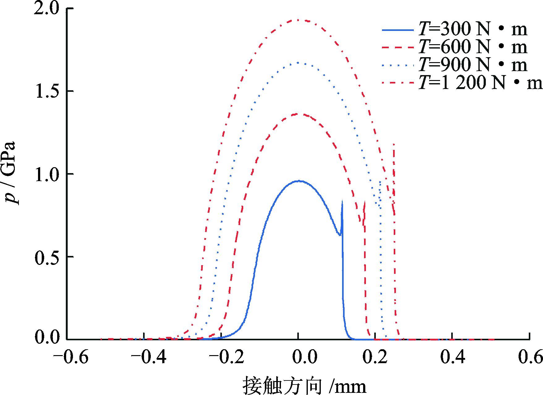
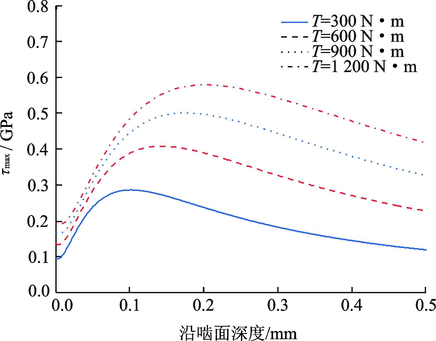
为研究不同工况对疲劳寿命的影响,考察一定转速下不同扭矩和一定扭矩下不同转速对齿面压力和次表面应力的影响。图 12~14为N=1 800 r/min时不同扭矩对齿面压力和次表面应力的影响。随着输入扭矩增大,齿面压力增加,接触区变宽,二次压力峰的影响逐渐减小。图 13为z=0.05 mm处的交变剪应力时间历程,图 14为啮合点处沿齿面深度方向的最大剪应力分布,随着输入扭矩增大,在平行于齿面方向交变剪应力幅值增加,在沿深度方向最大剪应力增大,其极值位置所在深度增大。
|
图 12 不同扭矩下压力分布 Figure 12 Distribution of pressure under different torque |

|
图 13 不同扭矩下z=0.05 mm处的剪应力分布 Figure 13 Distribution of shear stress in depth of z=0.05 mm under different torque |
|
图 14 不同扭矩下沿齿面深度主剪应力分布 Figure 14 Distribution of principal shear stress along depth under different torque |
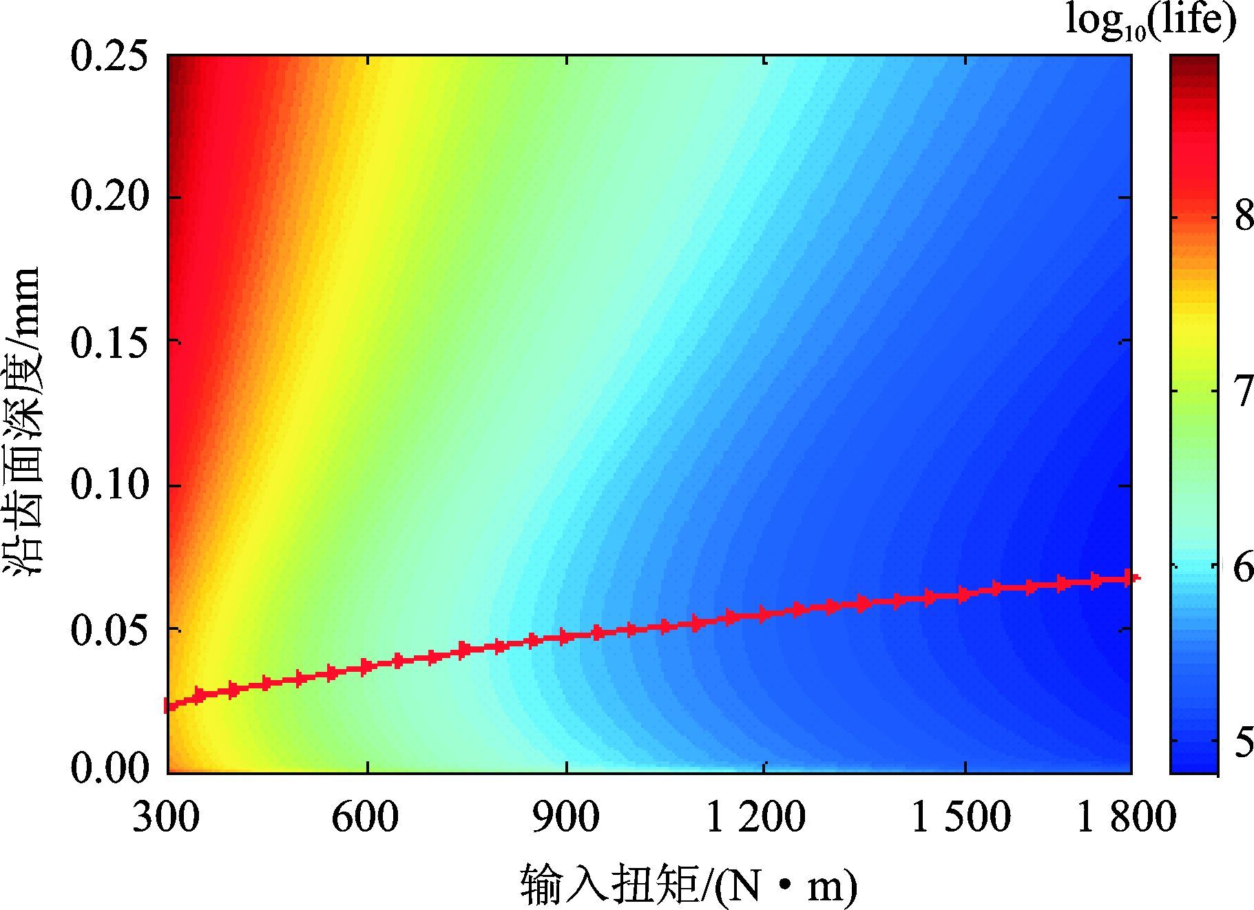
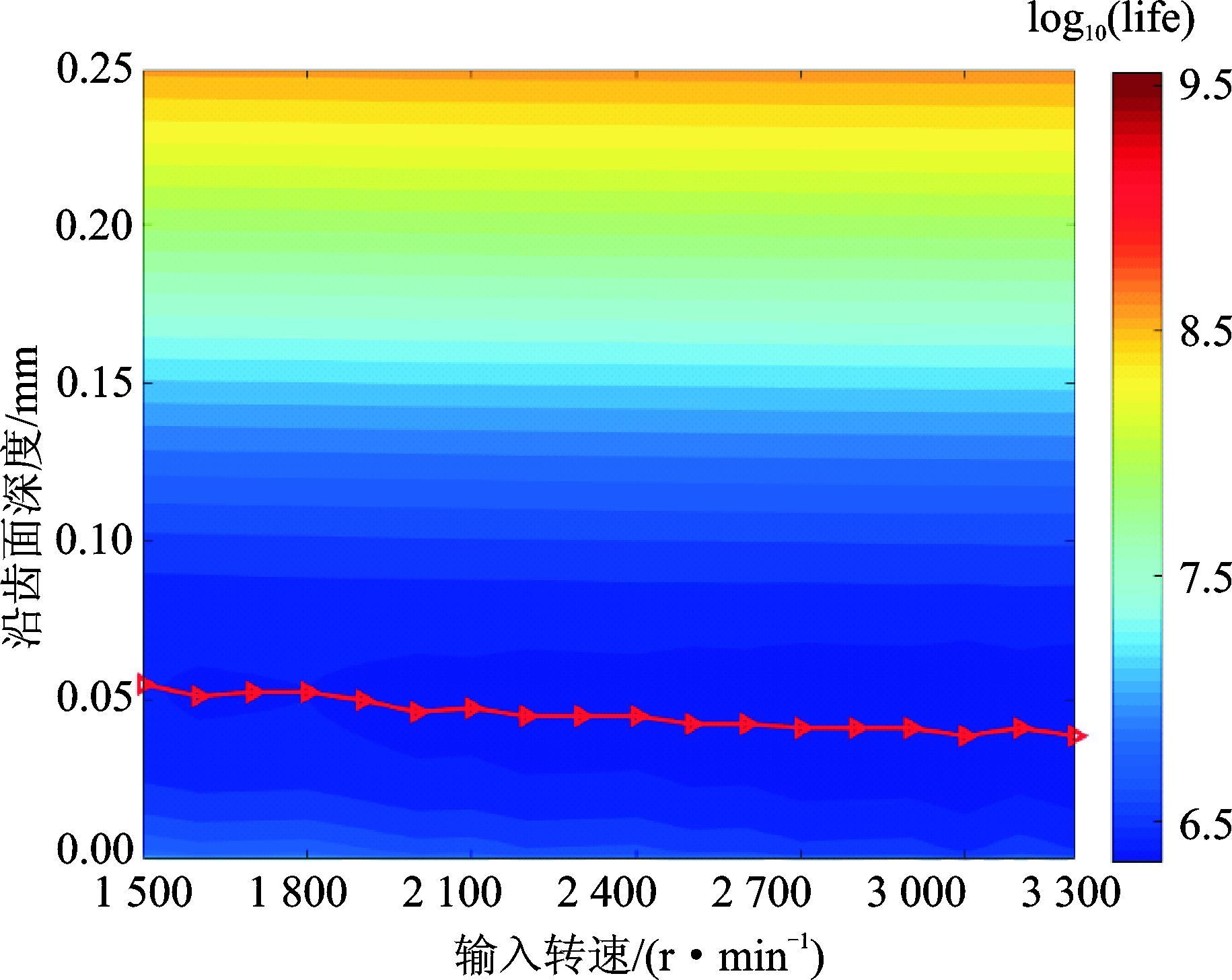
图 15为扭矩从300 N·m增至1 800 N·m的疲劳寿命分布,当扭矩增大至1 800 N·m时,疲劳寿命明显减小。在T=300 N·m时疲劳寿命为4.26×10⁷,在T=1 800 N·m时疲劳寿命为6.39×10⁴,扭矩和寿命的变化呈现非线性关系。扭矩对裂纹萌生位置有重要影响,当扭矩增大时,裂纹萌生位置远离表面,二次压力峰的影响减小,油膜厚度降低,最大剪应力位置远离表面。图 16是扭矩T=700 N·m输入转速从1 500 r/min增至3 200 r/min时疲劳寿命分布,可见在等温牛顿流体情况下,转速的改变对疲劳寿命的影响并不明显。
|
图 15 不同扭矩下沿齿面深度疲劳寿命分布 Figure 15 Distribution of fatigue life along depth under different torque |
|
图 16 不同转速下沿齿面深度疲劳寿命分布 Figure 16 Distribution of fatigue life along depth under different speed |
4 结论
本文基于齿轮几何运动学特征以及润滑特性,建立直齿轮润滑接触分析模型,利用DC-FFT算法求解次表面应力场,结合临界平面准则计算接触疲劳寿命,对接触疲劳寿命和裂纹萌生位置进行预估,得到如下结论:
(1) DangVan准则比Matake准则预测结果更加保守,切应力分量是影响疲劳裂纹萌生的主要因素,但也要考虑正应力的影响。
(2) 由于润滑条件下齿面压力变化导致的次表面应力场变化改变了临界平面角,使等效疲劳参数减小,齿轮接触疲劳寿命增加;相对于赫兹干接触,弹流润滑下的接触疲劳寿命明显提高。
(3) 随着载荷增加,齿轮接触压力增大,二次压力峰的影响减弱,次表面应力最大值深度增加,疲劳寿命明显降低,裂纹萌生深度增加,且与工况的变化呈现非线性关系;在等温牛顿流体的情况下,转速变化对疲劳寿命的影响并不明显。
| [1] | Zhu D, Ren N, Wang Q J. Pitting life prediction based on a 3D line contact mixed EHL analysis and subsurface von Mises stress calculation[J]. Journal of Tribology, 2009, 131(4): 041501. DOI:10.1115/1.3195040 |
| [2] | Li S, Kahraman A, Klein M. A fatigue model for spur gear contacts operating under mixed elastohydrodynamic lubrication conditions[J]. Journal of Mechanical Design, 2012, 134(4): 041007. DOI:10.1115/1.4005655 |
| [3] | Evans H P, Snidle R W, Sharif K J, et al. Analysis of micro-elastohydrodynamic lubrication and prediction of surface fatigue damage in micropitting tests on helical gears[J]. Journal of Tribology, 2012, 135(1): 011501. DOI:10.1115/1.4007693 |
| [4] | Brandäo J A, Seabra J H O, Castro J. Surface initiated tooth flank damage[J]. Wear, 2010, 268(1/2): 1–12. |
| [5] | Zhang H, Wang W, Zhang S, et al. Modeling of finite-length line contact problem with consideration of two free-end surfaces[J]. Journal of Tribology, 2015, 138(2): 1–10. |
| [6] | Liu M, Zhu C, Liu H, et al. Effects of working conditions on TEHL performance of a helical gear pair with non-newtonian fluids[J]. Journal of Tribology, 2014, 136(2): 325. |
| [7] | Liu M, Zhu C, Liu H, et al. Parametric studies of lubrication performance of a helical gear pair with non-Newtonian fluids[J]. Journal of Mechanical Science & Technology, 2016, 30(1): 317–326. |
| [8] | Liu H, Mao K, Zhu C, et al. Spur gear lubrication analysis with dynamic loads[J]. Tribology Transactions, 2013, 56(1): 41–48. DOI:10.1080/10402004.2012.725805 |
| [9] | Zhu C, Sun Z, Liu H, et al. Effect of tooth profile modification on lubrication performance of a cycloid drive[J]. Proceedings of the Institution of Mechanical Engineers Part J Journal of Engineering Tribology, 2015, 229(7): 785–794. DOI:10.1177/1350650115570402 |
| [10] | Weck M, Kruse A, Gohritz A. Determination of surface fatigue of gear material by roller tests[J]. Journal of Mechanical Design, 1978, 100(3): 112. |
| [11] | Aslantas K, Tasgetiren S. A study of spur gear pitting formation and life prediction[J]. Wear, 2004, 257(11): 1167–1175. DOI:10.1016/j.wear.2004.08.005 |
| [12] | Pedrero J I, Pleguezuelos M, Artés M, et al. Load distribution model along the line of contact for involute external gears[J]. Mechanism and Machine Theory, 2010, 45(5): 780–794. DOI:10.1016/j.mechmachtheory.2009.12.009 |
| [13] | Johnson K L. Contact mechanics[M]. Cambridge: Cambridge University Press, 1985. |
| [14] | Liu S, Wang Q. Studying contact stress fields caused by surface tractions with a discrete convolution and fast fourier transform algorithm[J]. Journal of Tribology, 2002, 124(1): 36. DOI:10.1115/1.1401017 |
| [15] | Snidle R W, Evans H P, Qiao H. Comparison of fatigue model results for rough surface elastohydrodynamic lubrication[J]. Journal of Engineering Tribology, 2008, 222(3): 381–393. |
| [16] | Karolczuk A, Macha E. A review of critical plane orientations in multiaxial fatigue failure criteria of metallic materials[J]. International Journal of Fracture, 2005, 134(3/4): 267–304. |
| [17] | Matake T. An explanation on fatigue limit under combined stress[J]. Bulletin of JSME, 1977, 20(14): 257–263. |
| [18] | DangVan K, Griveau B, Message O. On a new multiaxial fatigue limit criterion:Theory and application[J]. Biaxial and Multiaxial Fatigue, EGF 3, 1989: 459–478. |
| [19] | Osman T, Velex P. A model for the simulation of the interactions between dynamic tooth loads and contact fatigue in spur gears[J]. Tribology International, 2012, 46(1): 84–96. DOI:10.1016/j.triboint.2011.03.024 |
| [20] | Liu Y, Mahadevan S. Multiaxial high-cycle fatigue criterion and life prediction for metals[J]. International Journal of Fatigue, 2005, 27(7): 790–800. DOI:10.1016/j.ijfatigue.2005.01.003 |
 2016, Vol. 48


